Week Three Blog:
1. Compare the calculated and measured equivalent resistance values between the nodes A and B for three circuit configurations given below.
For the three circuits below we found the equivalent resistance value by calculating the resistance value and comparing our results with the measured reading from the DMM. Our resistors for the circuit are:
R1: 100 Ω
R2: 220 Ω
R3: 120 Ω
R4: 41 Ω

Our results were:

2. Apply 5V on a 120 Ω resistor. Measure the current by putting the multimeter in series and parallel. Why are they different?
When measuring currents over a resistor you must connect the leads in series with the resistor. If you connect the leads in parallel the measured current will be zero because the current follows the easiest path which is through the resistor, completely surpassing the DMM. We proved this experimentally. When we measured the current in series, it came out to 40.7mA. When we measured the current in parallel, there was no current.
3. Apply 5V to two resistors (47Ω and 120Ω) that are in series. Compare the measured and calculated values of voltage and current values on each resistor.
4. Apply 5V to two resistors (47Ω and 120Ω) that are in parallel. Compare the measured and calculated values of voltage and current values on each resistor.
5. Compare the calculated and measured values of the voltages of the following current and voltage for the circuit below:
a. Current on 2kΩ resistor,


a)

The above circuit has a measured equivalent resistance of 0.563kΩ.
7. Measure the equivalent resistance with and without the 5V power supply. Are the different? Why?
Without the power supply, the DMM reads that the equivalent resistance is 0.563kΩ. But with the power supply adding 5V to the circuit, the DMM reads 0M for the equivalent resistance. This difference comes from how the DMM measures the resistance. The DMM supplies a small current to the circuit and measures the resulting voltage. If you apply an outside voltage to the circuit it throws off the measurement, and if you add 5V like we did, the reading is 0 because the voltage being applied to the circuit by the power supply is greater than any resulting voltage the DMM would have used.
8. Explain the operation of a potentiometer by measuring the resistance values between the terminals (there are 3 terminals, so there would be 3 combinations).
The potentiometer operates by spinning the dial to increase or decrease the resistance value. This only works if the two connections you have to the potentiometer has one being the center lead. Think of a 10kΩ potentiometer as a horse shoe with a total resistance of 10kΩ, at one end of shoe is lead 1 and at the other is lead 3. Lead 2 is attached to the dial and the piece the moves. Say for example you attach the DMM to leads 1 and 2, the resistance value will increase when you move lead 2 away from lead 1 and decrease when you move it closer.
Below is the measured resistance values for each pin combination and at three dial placements:
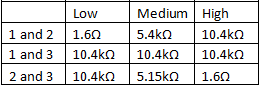
Below is a video explaining how we measured the resistance values on each lead of the potentiometer. Notice that if you add the resistance value from lead 1 to 2 and 2 to 3 together you get an overall resistance value that is around 10kΩ.
The minimum and maximum voltage values obtained in V1 are both 5V because the voltage drop across the resistance should be equal to the input voltage. When there is only one resistor, no matter its size, it will have a voltage drop value equal to the voltage input. Since the input voltage is always 5V, the voltage drop across any resistance value of the potentiometer is 5V.
10. How are V1 and V2 (voltages are defined with respect to ground) related and how do they change with the position of the knob of the pot?
V1 and V2 will always equal the input voltage when added together, in this case the input voltage is 5V so V1 + V2 = 5V. When the position of the knob of the pot is changed so that the potentiometer has a higher resistance value the voltage of V2 increases and the voltage of V1 decreases respectively. Likewise when the potentiometer has a lower resistance value the voltage across V1 increases and the voltage across V2 decreases respectively. Below is a video showing this happening.
11. For the circuit shown in the video below, YOU SHOULD NOT turn down the potentiometer all the way down to reach 0Ω. Why?
Because when you turn down the potentiometer that far you are effectively shorting the voltage source creating a very high current which will destroy your potentiometer.
The current value for 1kΩ will be 5mA, this value will not change because the voltage across the resistor does not change and the resistor's resistance does not change. The current across the 10kΩ pot will vary based on the resistance value of the potentiometer at that time. The currents across the 1kΩ resistor and 10kΩ will equal the current measured at the voltage source, but even that current will change based on the resistance value of the potentiometer changing the equivalent resistance of the circuit.
13. Explain what a voltage divider is and how it works based on your experiments.
A voltage divider consists of two or more resistors in
series to separate the input voltage into different controlled voltages. The
voltage over each resistor is a fraction of the input voltage. If all of the
voltages are added together, they are to equal the input voltage.
14. Explain what a current divider is and how it works based on your experiments.
A current divider consists of two or more resistors in
parallel to separate the current through each resistor. The current through
each resistor is a fraction of the input current. If the measured current
through each resistor is added together, it will be equal to the input current.
Hey, I like where the blog is headed so far. I think it'd make more sense if some of the prompts were included.
ReplyDeleteI like how it's starting to look, just fix up the formatting and it will look great!
ReplyDelete#3, 4, and 5; no explanations.
ReplyDeleteNo captions for figures (also tables need captions)
I cannot see the videos (firefox, explorer, chrome). Let me know if you fix it.