1. You will use the OPAMP in "open-loop" configuration in this part, where input signals will be applied directly to the pins 2 and 3.
a. Apply 0V to the inverting input. Sweep the non-inverting input (Vin) from -5V to 5V with 1V steps. Take more steps around 0V. Create a table for Vin and Vout. Plot the data. Disuss your results. What would be the ideal plot?


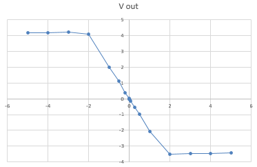
Table of Vin and Vout for non-inverting amplifier

Plot of Vin and Vout for table above
The ideal plot would show Vout ranging from 5V to -5V. Our amplifier was not ideal, so there was some loss of voltage. There was a very high gain because of the open loop, so instead of amplifying the voltage proportionally, it just reaches the maximum and minimum values.
b. Repeat part A for the non-inverting input.

Table of Vin and Vout for inverting amplifier

Plot of Vin and Vout for table above
The ideal plot would range from -5V to 5V. This is because of the same reason listed above. This is equal and opposite to the reading above because it is inverted.
2. Create a non-inverting amplifier. (R2= 2K, R1=1K). Sweep Vin from -10V to 10V with 1V steps. Create a table for Vin and Vout. Plot the measured and calculated data together.


Table for Vin and Vout of non-inverting amplifier

Plot for Vin and Vout for table above
This is the data gathered from the non-inverting amplifier with R1=1K and R2=2K. It's very similar to the plot we expected to see. Instead of an immediate switch at 0V like the open experiments, there is a linear rise from negative to positive output voltage.
3. Repeat part 2 with an inverting amplifier.

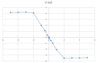
Table of Vin and Vout for an inverting amplifier
Plot of Vin and Vout for the table above
These observations are equal and opposite to the values above because it is an inverting amplifier.
4. Explain how an OPAMP works. How come the gain of the OPAMP in the open loop configuration is too high but inverting/non-inverting amplifier configurations provide such a small gain?
An OPAMP generates a higher output voltage than what is input. It is used to amplify a signal larger than normal. When the OPAMP is in the open loop configuration, it produces a gain so high that the voltage maxes out at the upper and lower limits long before before it reaches a half of a volt. The inverting/non-inverting amplifier configurations provide a small gain because the resistors keep the difference between the positive and negative inputs smaller.
Temperature Control:
As the heat applied to the temperature sensor increases, the voltage output will increase linearly as well.
Relay:
1. Connect your DC power supply to pin 2 and ground pin 5. Set your power supply to 0V. Switch your multimeter to measure the resistance mode; use your multimeter to measure the resistance between pin 4 and pin 1. Do the same measurement between pin 3 and pin 1. Explain your finding.
The resistance value between pin 4 and pin 1 was 0Ω. The resistance value between pin 3 and pin 1 was 200Ω.
2. Now sweep your DC power supply from 0V to 8V and back to 0V. What do you observe at the multimeter? Did you hear a clicking sound? How many times? What is the threshold voltage value that cause the switching?
When we hear the relay make a clicking sound, we know that it has "switched" between pin 3 and pin 4. The threshold voltage value to change pins is 6V when we increased the voltage. When decreasing, the lower threshold voltage value was around 2.5V. These are the points at which you hear the clicking sound.
3. How does the relay work? Apply a seperate DC voltage of 5V to pin 1. Check the voltage value of pin 3 and pin 4 while switching the relay.
When reading the voltage values at pin 3 and 4, we noticed that while one pin has a readable voltage value, the other pin reads 0V. After reaching the threshold voltage value, allowing the relay to switch, the pin that originally had a readable value now reads 0V and the pin that read 0V orginally now reads the value that the other pin originally read.
LED + Relay
Operational Amplifier:
1. Connect the power supplies to the op-amp. Show the operation of LM 124 operational amplifier in DC mode with a non-inverting amplifier configuration. Choose any opamp in the IC.


2. Use your temperature sensor as your input. Do you think you can generate enough voltage to trigger the relay.
No, we can not generate enough voltage with this set up. We need roughly 6V to trigger the relay. The temperature sensor would output only around 1.6-1.7V. To get this to 6V, we would need almost 400 degrees Celsius, which would most definitely melt the breadboard.
3. We added a non-inverting amplifier to the V out of the temperature sensor to increase it's signal large enough to turn on the LED.

4.
An OPAMP generates a higher output voltage than what is input. It is used to amplify a signal larger than normal. When the OPAMP is in the open loop configuration, it produces a gain so high that the voltage maxes out at the upper and lower limits long before before it reaches a half of a volt. The inverting/non-inverting amplifier configurations provide a small gain because the resistors keep the difference between the positive and negative inputs smaller.
Temperature Control:
As the heat applied to the temperature sensor increases, the voltage output will increase linearly as well.
Relay:
1. Connect your DC power supply to pin 2 and ground pin 5. Set your power supply to 0V. Switch your multimeter to measure the resistance mode; use your multimeter to measure the resistance between pin 4 and pin 1. Do the same measurement between pin 3 and pin 1. Explain your finding.
The resistance value between pin 4 and pin 1 was 0Ω. The resistance value between pin 3 and pin 1 was 200Ω.
2. Now sweep your DC power supply from 0V to 8V and back to 0V. What do you observe at the multimeter? Did you hear a clicking sound? How many times? What is the threshold voltage value that cause the switching?
When we hear the relay make a clicking sound, we know that it has "switched" between pin 3 and pin 4. The threshold voltage value to change pins is 6V when we increased the voltage. When decreasing, the lower threshold voltage value was around 2.5V. These are the points at which you hear the clicking sound.
3. How does the relay work? Apply a seperate DC voltage of 5V to pin 1. Check the voltage value of pin 3 and pin 4 while switching the relay.
When reading the voltage values at pin 3 and 4, we noticed that while one pin has a readable voltage value, the other pin reads 0V. After reaching the threshold voltage value, allowing the relay to switch, the pin that originally had a readable value now reads 0V and the pin that read 0V orginally now reads the value that the other pin originally read.
LED + Relay
This video shows the relay switching. When the voltage is increased, there is a clicking sound and the LED lights on. This shows that the threshold voltage value has been reached. The voltage is decreased and the LED shuts off when the lower threshold value is reached.
Operational Amplifier:
1. Connect the power supplies to the op-amp. Show the operation of LM 124 operational amplifier in DC mode with a non-inverting amplifier configuration. Choose any opamp in the IC.
Table for R1=1000 and R2=2200
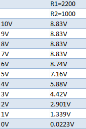
Table for R1=2200 and R2=1000
Table for R1=1000 and R2=12000
Table for R1=1000 and R2=3000
Table for R1=2200 and R2-3000
As you can see in all 5 of these experiments, all of them have a very similar maximum voltage value. This tells us that the upper limit of the amplifier is unaffected by the resistor configuration. The only difference between the graphs is the rate at which the output voltage drops to zero as in the input voltage goes to zero.
2. Use your temperature sensor as your input. Do you think you can generate enough voltage to trigger the relay.
No, we can not generate enough voltage with this set up. We need roughly 6V to trigger the relay. The temperature sensor would output only around 1.6-1.7V. To get this to 6V, we would need almost 400 degrees Celsius, which would most definitely melt the breadboard.
3. We added a non-inverting amplifier to the V out of the temperature sensor to increase it's signal large enough to turn on the LED.

4.
This formatting seems okay, I'd recommend bolding the questions though so it's easier to differentiate.
ReplyDeleteBetter late than never, as I always say.
ReplyDeleteThis comment has been removed by the author.
ReplyDeleteNumber your figures and tables next time.
ReplyDelete#2, 3: Plot should have had the theoretical data as well. (-2)
#4 is not correct. We will talk about it though.
Explanation of the design is missing. (-2)
Bonus video! (+2)